
Understanding SMT Meaning and DC Voltage Symbols in Modern Electronics | PCBasic
In modern electronics design and manufacturing, a clear understanding of SMT meaning and the correct interpretation of the DC voltage symbol are fundamental skills for engineers, technicians, and product developers. From schematic design to PCB assembly and final testing, these two concepts play a critical role in ensuring circuit functionality, manufacturability, and long-term reliability. As electronic products become smaller, faster, and more complex, mastering both surface-mount technology and electrical schematic symbols is no longer optional—it is essential.
What Does SMT Mean in Electronics?
SMT, or Surface Mount Technology, refers to the method of mounting electronic components directly onto the surface of a printed circuit board (PCB). Unlike traditional through-hole technology, SMT components do not require drilled holes, allowing for higher component density and more compact designs.
Today, SMT is the dominant assembly method used in consumer electronics, industrial controls, automotive electronics, and medical devices. Components such as resistors, capacitors, ICs, and BGAs are placed with high-speed pick-and-place machines and soldered using reflow soldering processes. This approach improves electrical performance while significantly reducing board size and production cost.
Why SMT Is Essential in Modern PCB Assembly
The widespread adoption of SMT is driven by several key advantages:
- Miniaturization: Smaller components allow for compact and lightweight products
- Higher circuit density: More functionality in less space
- Improved signal performance: Shorter interconnections reduce parasitic effects
- Automated manufacturing: Higher consistency and scalability
- Cost efficiency: Ideal for both prototyping and mass production
Because of these benefits, nearly all modern PCBA projects rely on SMT as the core assembly technology.
Understanding DC Voltage Symbols in Circuit Schematics
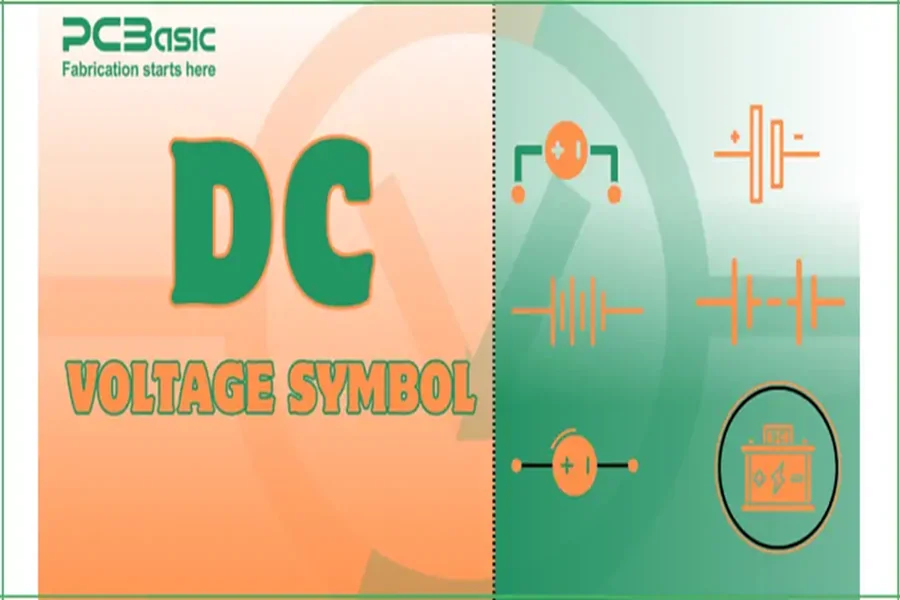
Electronic schematics use standardized symbols to communicate electrical intent clearly and unambiguously. Among them, the DC voltage symbol represents a constant, unidirectional electrical potential—commonly supplied by batteries, DC power adapters, or regulated power supplies.
Unlike AC voltage, DC voltage maintains a fixed polarity, making it the foundation of most electronic circuits. Recognizing DC voltage symbols correctly is critical for avoiding polarity errors, protecting components, and ensuring safe operation during testing and troubleshooting.
Common Applications of DC Voltage in Electronics
DC voltage is used throughout electronic systems, including:
- Power rails for microcontrollers and ICs
- Biasing of analog circuits
- Battery-powered devices
- Logic level references
- Motor control and driver circuits
Misinterpreting DC voltage symbols can lead to incorrect wiring, component damage, or complete system failure—especially in sensitive SMT-based designs.
The Relationship Between SMT and DC Voltage Design
SMT assembly and DC voltage design are closely linked. Surface-mount components often operate at low DC voltages with tight tolerance requirements. Poor voltage regulation, incorrect polarity, or unstable DC rails can directly affect solder joints, IC performance, and long-term reliability.
In professional PCB assembly, engineers must consider power integrity, grounding, and voltage distribution early in the design stage to ensure SMT components perform as intended after assembly.
Best Practices for Engineers and Designers
To achieve reliable results in modern electronics projects:
- Fully understand SMT component packages and placement rules
- Read and apply DC voltage symbols accurately in schematics
- Verify polarity before assembly and testing
- Design stable DC power networks for SMT layouts
- Collaborate with experienced PCB assembly manufacturers
These practices help reduce rework, improve yield, and accelerate time to market.
PCBasic: Supporting SMT and PCBA Excellence
At PCBasic, we specialize in professional PCB fabrication and SMT assembly services for prototypes and small-to-medium production runs. Our engineering team ensures accurate implementation of SMT designs, correct handling of DC power requirements, and strict quality control throughout the manufacturing process.
By combining advanced SMT production lines with rigorous electrical verification, PCBasic helps customers turn well-designed schematics into reliable, manufacturable electronic products.
Conclusion
Understanding SMT meaning and DC voltage symbols is a foundational requirement in modern electronics. Together, they bridge the gap between circuit design and real-world manufacturing. As devices continue to evolve toward higher integration and smaller form factors, engineers who master these fundamentals are better equipped to design reliable, efficient, and scalable electronic systems.
If you are developing your next PCB project, ensuring clarity in both SMT design and DC voltage interpretation is the first step toward success.